この記事では「論理回路」に限って扱います。
\LaTeX で論理回路を描くのは、まぁひかえめに言っても苦行なのですが、それはさておきます。
代表的な方法
私が知る限り現在の代表的な方法としては以下の3種類があります。
TikZ の circuits.logic ライブラリ
長所として、
- TikZ で閉じている
のですが、
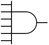
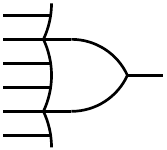
- 記号をはみだすような多入力 (下図参照) が (おそらく) 描けない
- 用意されている部品が限られている (たぶんフリップフロップとかはない)
という欠点もあります。
CircuiTikZ
なんとなく良さげな名前ですが、論理回路に限っていえば利点が見当りません…
欠点としては、
- American style の記号が正しくない (MIL/ANSI でも DIN でもない)
- 三入力までしか描けない?
で、全く美しくない、というのが正直な感想です。
Circuit macros
- かなり柔軟
- TikZ/PSTricks/PDF などいろいろ出力できる
で非常に良い感じなのですが、
- M4 マクロなので、その記法を覚える必要あり
- M4 マクロから変換の手間が必要
と、習得のコストが大きめです。
なお、以前は TeX Live に含まれていませんでしたが、TeX Live 2019 以降で追加されたようです。
それぞれのサンプル
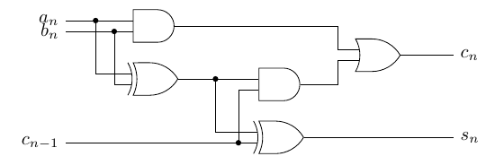
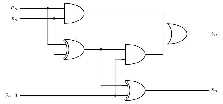
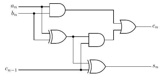
試しにそれぞれで Full adder を書いてみましたので最後に付けます。
TikZ/circuits.logic と CircuiTikZ はかなり似ているので、一方から他方への書き換えは比較的楽です。
見ての通り、TikZ/circuits.logic と Circuit macros はかなり綺麗な出力が得られますが、CircuiTikZ はちょっとアレすぎます。ということで、私的には論理回路を描くのに CircuiTikZ は完全にナシです。
大きめの回路では Circuit macros を使うのが現時点ではベストではないでしょうか (Full adder くらいの規模だとちょっと悩む)。
なお、Circuit macros には、
- Cirkuit (http://wwwu.uni-klu.ac.at/magostin/cirkuit.html)
- PyCirkuit (https://pypi.org/project/pycirkuit/)
なるフロントエンドがあるようですが、私自身は試してません。
TikZ/circuits.logic と CircuiTikZ はもうちょっと綺麗なソースコードで書けそうな気もしますが、使う予定がないのであまり追求してません。
TikZ/circuits.logic
\documentclass{article}

\usepackage{tikz}
\usetikzlibrary{circuits.logic.US}

\begin{document}

% http://tex.stackexchange.com/questions/32839/drawing-circuit-diagrams-with-logic-gates-in-latex
\tikzstyle{branch}=[fill,shape=circle,minimum size=3pt,inner sep=0pt]

\begin{center}
  \begin{tikzpicture}[circuit logic US]
    % Half adder 2
    \draw (4,1) node[xor gate] (xor2) {};
    \draw (xor2)+(0,1) node[and gate] (and2) {};

    % Half adder 1
    \draw (and2.input 1)+(-2,0) node[xor gate] (xor1) {};
    \draw (xor1)+(0,1) node[and gate] (and1) {};

    % Carry
    \draw ($0.5*(and1)+0.5*(and2)+(3,0)$) node[or gate] (or) {};

    % connection between AND1 and XOR1
    \draw (and1.input 1) to ++(-0.70,0) node [branch] {} |- (xor1.input 1);
    \draw (and1.input 2) to ++(-0.35,0) node [branch] {} |- (xor1.input 2);

    % connection between HA1 and HA2
    \draw (xor1.output) -- (and2.input 1);

    % connection between AND1 and XOR1
    \draw (xor1.output)  to ++( 0.70,0) node [branch] {} |- (xor2.input 1);
    \draw (xor2.input 2) to ++(-0.35,0) node [branch] {} |- (and2.input 2);

    % connection between AND1,2 and OR
    \draw (or.input 2) -- ++(-0.4,0) |- (and2.output);
    \draw (or.input 1) -- ++(-0.4,0) |- (and1.output);

    % outputs
     \draw (or.output) -- ++(1,0) node[right] (output) {$c_n$};
     \draw (xor2.output) -- ($($(or.output)+(1,0)$)!(xor2.output)!($(or.output)+(1,1)$)$) node[right] {$s_n$};

    % inputs
     \draw (xor2.input 2) -- ($(0,1)!(xor2.input 2)!(0,0)$) node[left] {$c_{n-1}$};
     \draw (and1.input 1) -- ($(0,1)!(and1.input 1)!(0,0)$) node[left] {$a_n$};
     \draw (and1.input 2) -- ($(0,1)!(and1.input 2)!(0,0)$) node[left] {$b_n$};
  \end{tikzpicture}
\end{center}

\end{document}CircuiTikZ
\documentclass{article}
\usepackage[americanports]{circuitikz}
\begin{document}

\begin{center}
  \begin{circuitikz}
    % Half adder 2
    \draw (7,1) node[xor port] (xor2) {};
    \draw (xor2)+(0,2) node[and port] (and2) {};

    % Half adder 1
    \draw (and2.in 1)+(-2,0) node[xor port] (xor1) {};
    \draw (xor1)+(0,2) node[and port] (and1) {};

    % Carry
    \draw ($0.5*(and1)+0.5*(and2)+(4,0)$) node[or port] (or) {};

    % connection between AND1 and XOR1
    \draw (and1.in 1) to [short,-*] ++(-0.70,0) |- (xor1.in 1);
    \draw (and1.in 2) to [short,-*] ++(-0.35,0) |- (xor1.in 2);

    % connection between HA1 and HA2
    \draw (xor1.out) -- (and2.in 1);

    % connection between AND1 and XOR1
    \draw (xor1.out)  to [short,-*] ++( 0.70,0) |- (xor2.in 1);
    \draw (xor2.in 2) to [short,-*] ++(-0.35,0) |- (and2.in 2);

    % connection between AND1,2 and OR
    \draw (and2.out) -| (or.in 2);
    \draw (and1.out) -| (or.in 1);

    % outputs
    \draw (or.out) -- ++(1,0) node[right] (out) {$c_n$};
    \draw (xor2.out) -- ($($(or.out)+(1,0)$)!(xor2.out)!($(or.out)+(1,1)$)$) node[right] {$s_n$};

    % inputs
    \draw (xor2.in 2) -- ($(0,1)!(xor2.in 2)!(0,0)$) node[left] {$c_{n-1}$};
    \draw (and1.in 1) -- ($(0,1)!(and1.in 1)!(0,0)$) node[left] {$a_n$};
    \draw (and1.in 2) -- ($(0,1)!(and1.in 2)!(0,0)$) node[left] {$b_n$};
  \end{circuitikz}
\end{center}

\end{document}
Circuit macros
(図では線の太さにバラつきがありますが、レンダリングの問題で、実際には同じ太さで描かれています。)
dnl fadder.m4

.PS

log_init

AND1: AND_gate
line left AND_wd*2*L_unit from AND1.In1; "$a_n$" rjust
line left AND_wd*2*L_unit from AND1.In2; "$b_n$" rjust

XOR1: XOR_gate at AND1-(0,AND_ht*2)*L_unit
line left AND_wd/2*L_unit from XOR1.In1 \
    then up AND_ht*2*L_unit ;  dot
line left AND_wd*L_unit from XOR1.In2 \
    then up AND_ht*2*L_unit ; dot

AND2: AND_gate at XOR1+(AND_wd*2.5,-AND_ht/4)*L_unit
line from XOR1.Out to AND2.In1

OR1: OR_gate at AND2+(AND_wd*2,AND_ht)*L_unit
line left 0.5*AND_wd*L_unit from OR1.In1
line to (Here.x, AND1.Out.y) then to AND1.Out

line left 0.5*AND_wd*L_unit from OR1.In2
line to (Here.x, AND2.Out.y) then to AND2.Out

line right AND_wd*L_unit from OR1.Out; "$c_n$" ljust

XOR2: XOR_gate at AND2+(0,-AND_ht*2)*L_unit
line left AND_wd/2*L_unit from AND2.In2
line to (Here.x, XOR2.In2.y); dot

line from XOR2.In2 to (AND1.In1.x - AND_wd*2*L_unit, XOR2.In2.y)
"$c_{n-1}$" rjust

line left AND_wd*L_unit from XOR2.In1
line to (Here.x, AND2.In1.y); dot

line from XOR2.Out to (OR1.Out.x + AND_wd*L_unit, XOR2.Out.y); "$s_n$" ljust

.PE
% example.tex
\documentclass{article}
\usepackage{tikz}
\begin{document}
\begin{center}
% m4 -I /usr/local/share/Circuit_macros liblog.m4 pgf.m4 fadder.m4 > fadder.pic
% dpic -g fadder.pic > fadder.tex
\input{fadder}
\end{center}
\end{document}